Weer aan t beunen,Peer
| USA Pick-up Trucks https://www.usatrucks.nl/forum/ |
|
| kleppen stellen k30 https://www.usatrucks.nl/forum/viewtopic.php?f=11&t=1307 |
Pagina 1 van 1 |
| Auteur: | peerkehemi [ za jan 17, 2009 20:07 ] |
| Berichttitel: | kleppen stellen k30 |
wie weet of dat de kleppen van een chevy k30 nog zelf moet stellen of dat ze zelf stellend zijn . |
|
| Auteur: | johnhemi [ za jan 17, 2009 20:25 ] |
| Berichttitel: | Re: kleppen stellen k30 |
Weer aan t beunen,Peer |
|
| Auteur: | peerkehemi [ za jan 17, 2009 20:37 ] |
| Berichttitel: | Re: kleppen stellen k30 |
johnhemi schreef: Weer aan t beunen,Peer je moet toch wat john .een maatje van mij .hij doet de tuin ik de chevy |
|
| Auteur: | johnhemi [ za jan 17, 2009 20:42 ] |
| Berichttitel: | Re: kleppen stellen k30 |
Goed geregeld ,peer Zo'n maat heb ik ook,ik heb bij Hans met de chevy ,vanmiddag een koeie hoorn op zijn truckie gezet Hans zijn vrouw helpt mijn vriendin weer met t opzetten van de eigen zaak per 1 februari |
|
| Auteur: | Mobart [ za jan 17, 2009 20:55 ] |
| Berichttitel: | Re: kleppen stellen k30 |
wat voor blok ligt erin? |
|
| Auteur: | peerkehemi [ za jan 17, 2009 21:21 ] |
| Berichttitel: | Re: kleppen stellen k30 |
Mobart schreef: wat voor blok ligt erin? 6.2 diesel bart . |
|
| Auteur: | ford1955 [ za jan 17, 2009 21:36 ] |
| Berichttitel: | Re: kleppen stellen k30 |
Volgens mij hydraulisch,maar moet ik effe maandag opzoeken op me werk Peer,je hoort van me |
|
| Auteur: | Mobart [ za jan 17, 2009 21:42 ] |
| Berichttitel: | Re: kleppen stellen k30 |
Een antwoord op een US-diesel-forum: Citaat: Unless you have more than 300,000 miles or you just did a cam replacement I would not touch it. Recommendations by Cummins Verder dit nog gevonden, maar is volgens mij voor een 5.9L, ik weet niet of dat uitmaakt... Tools needed : A set of feeler gauges Open end wrenches 9/16 in or a 14mm, 10mm Allen key set Socket set 10mm, a 7/8 in or 22mm Torque wrench Inspection mirror Optional tools Cummins barring tool P/N 3377371 Flashlight Specifications: Rocker arm locknut 18 ft lbs Intake valve - .010 Exhaust valve - .020 Valve Order TDC Cylinder # 1 In + Ex, 2 In, 3 Ex, 4 In, 5 Ex BDC Cylinder # 2 Ex, 3 In, 4 Ex, 5 In, 6 In+Ex Procedure : Engine must be cold prior to setting the valve lash. Overnight cool off is ideal. 1. Remove the valve cover. There are 5 bolts that hold the valve cover to the head. Use a 10mm socket wrench or nutdriver to loosen the bolts. You will not be able remove the bolt completely. After all 5 are loose pick up the cover and remove the cover. It can be tricky to remove. Be careful not to damage the rubber valve cover gasket. 2. Remove the injection pump drive cover. The cover is simply the round plastic piece that the breather tube connects to on the timing cover. Remove the breather tube from the cover. The cover simply screws onto the timing cover. Rotate counter clockwise to remove. 3. Rotate the crankshaft so that cylinder #1 is at Top Dead Center (TDC). This is accomplished with one of two ways: 3a. One is by using the Cummins Barring tool and a 1/2 in drive. Remove the rubber plug on the front passenger side of the bell housing. Insert the barring tool and turn the wrench. This method engages the flywheel directly to rotate the crankshaft. You can rotate the crankshaft either direction. 3b. The other method uses the alternator nut to rotate the crankshaft via the belt. Use either a 7/8in or a 22mm socket on the alternator pulley nut. Turn the wrench counter clockwise. If you turn the wrench clockwise the pulley will slip and not turn the belt at all. This method turn the crankshaft backward from the direction it normally turns while running. While using either of the two methods to rotate the crankshaft, you must watch the fuel pump drive gear to line up the timing marks (pictures below). There two markings on the timing case, one marked TDC and one marked BDC. Line up the timing mark on the drive gear with the TDC notch. 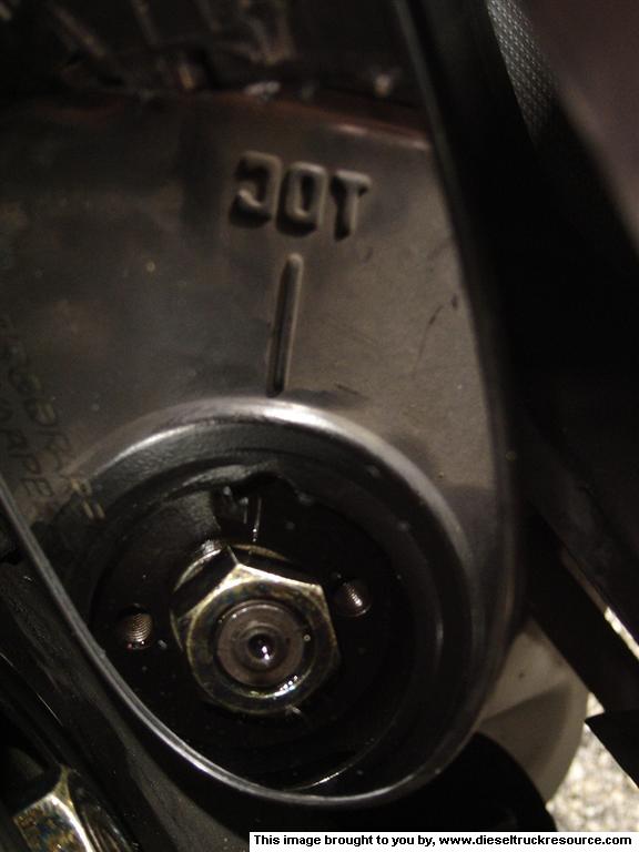 4. Setting the valves. Now that cylinder #1 is at TDC you can adjust some valve. Refer to the Valve Order listing to adjust the correct valves for TDC. Here you will need the open end wrenches, allen key set, feeler gauges, and the torque wrench. Start with cylinder #1. For reference the short rocker arm is for the intake valves, and the longer one is for the exhaust valves. (picture 1) The feeler gauge is used where the pivot stud meets the Y piece that engages the valves. Loosen the locknut on the rocker arm. Insert the feeler gauge, (picture 2) remember to use the proper size, .010 for intake and .020 for exhaust. Now use the proper allen key and adjust the allen head screw in the middle of the locknut. (picture 3) This adjusts the gap (valve lash) between the pivot stud and the Y piece. You will feel a slight drag on the feeler gauge once the gap is set correctly. Then remove the feeler gauge and with two hands hold the allen key steady while tightening the locknut, this is the most tricky part of the procedure. After tightening check the valve lash again and adjust as needed. Do all the valves listed in the Valve Order for TDC. After that is complete rotate the crankshaft one revolution until the timing mark is at the notch for BDC. Then do the valves listed for BDC. 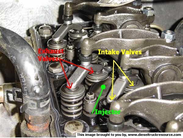 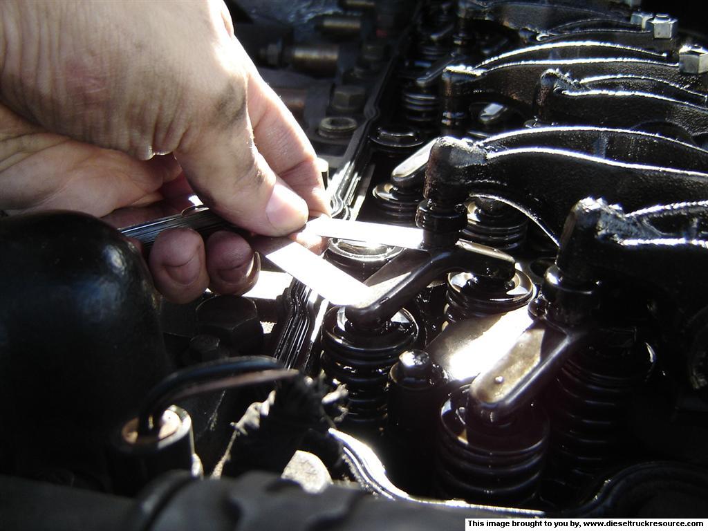 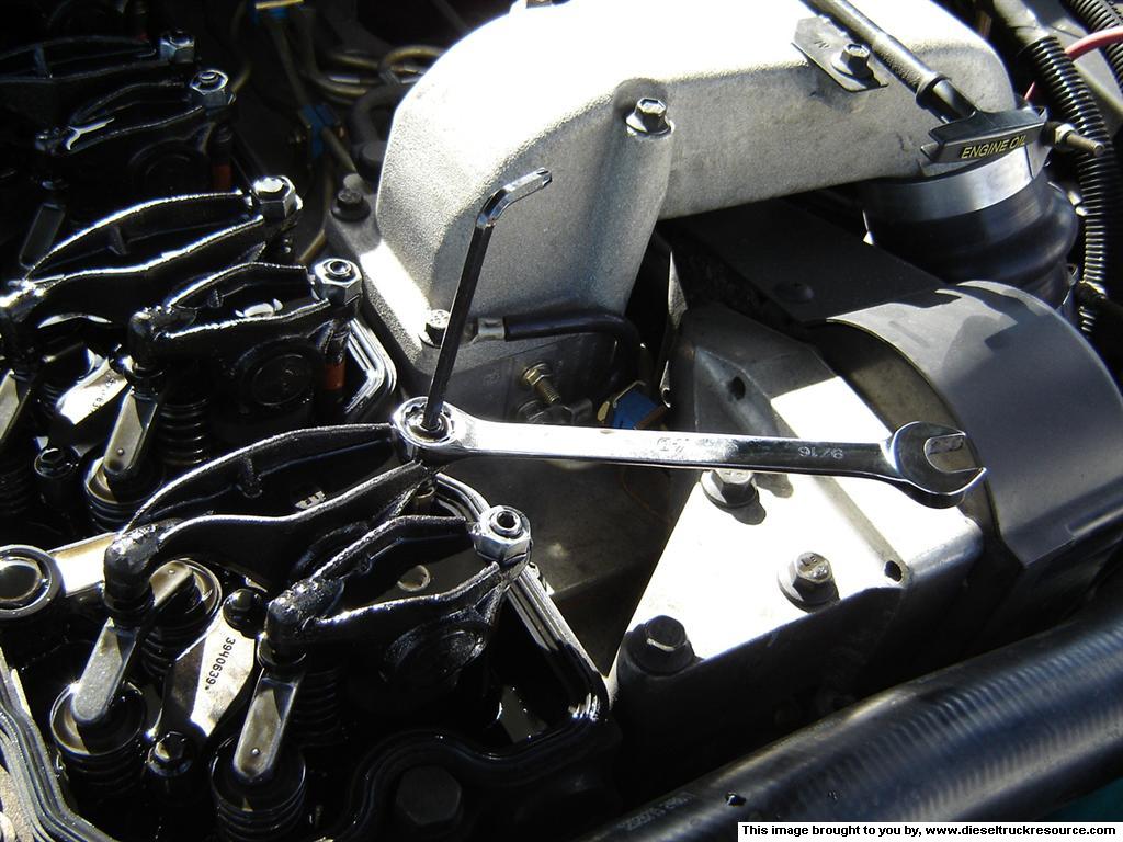 Tips and Techniques One great way to make sure of the proper valve measurement is to use what I call the Over Under technique. For example with the intake measurement of .010. A great way to know if you have the adjustment dead on is to use a feeler gauge that is .001 up and down from the intended measurement, so you would use a .011 and a .009 feeler gauge. When measuring the .009 gauge will fit very easily and the .011 gauge will not fit at all. Another tip is after all adjustment is done to rotate the crank shaft 2 revolutions and check all measurements again. This gives the springs a chance to compress and move the valves. After all valves are adjusted and checked replace the valve cover and the fuel pump drive cover and replace the breather tube. Ik hoop dat je hier iets mee kan!! grtz Bart |
|
| Auteur: | peerkehemi [ za jan 17, 2009 21:59 ] |
| Berichttitel: | Re: kleppen stellen k30 |
ford1955 schreef: Volgens mij hydraulisch,maar moet ik effe maandag opzoeken op me werk Peer,je hoort van me ik wacht het ff af marco |
|
| Auteur: | DutchYellowRam [ za jan 17, 2009 23:55 ] |
| Berichttitel: | Re: kleppen stellen k30 |
Mobart schreef: Een antwoord op een US-diesel-forum: Citaat: Unless you have more than 300,000 miles or you just did a cam replacement I would not touch it. Recommendations by Cummins Verder dit nog gevonden, maar is volgens mij voor een 5.9L, ik weet niet of dat uitmaakt... Tools needed : A set of feeler gauges Open end wrenches 9/16 in or a 14mm, 10mm Allen key set Socket set 10mm, a 7/8 in or 22mm Torque wrench Inspection mirror Optional tools Cummins barring tool P/N 3377371 Flashlight Specifications: Rocker arm locknut 18 ft lbs Intake valve - .010 Exhaust valve - .020 Valve Order TDC Cylinder # 1 In + Ex, 2 In, 3 Ex, 4 In, 5 Ex BDC Cylinder # 2 Ex, 3 In, 4 Ex, 5 In, 6 In+Ex Procedure : Engine must be cold prior to setting the valve lash. Overnight cool off is ideal. 1. Remove the valve cover. There are 5 bolts that hold the valve cover to the head. Use a 10mm socket wrench or nutdriver to loosen the bolts. You will not be able remove the bolt completely. After all 5 are loose pick up the cover and remove the cover. It can be tricky to remove. Be careful not to damage the rubber valve cover gasket. 2. Remove the injection pump drive cover. The cover is simply the round plastic piece that the breather tube connects to on the timing cover. Remove the breather tube from the cover. The cover simply screws onto the timing cover. Rotate counter clockwise to remove. 3. Rotate the crankshaft so that cylinder #1 is at Top Dead Center (TDC). This is accomplished with one of two ways: 3a. One is by using the Cummins Barring tool and a 1/2 in drive. Remove the rubber plug on the front passenger side of the bell housing. Insert the barring tool and turn the wrench. This method engages the flywheel directly to rotate the crankshaft. You can rotate the crankshaft either direction. 3b. The other method uses the alternator nut to rotate the crankshaft via the belt. Use either a 7/8in or a 22mm socket on the alternator pulley nut. Turn the wrench counter clockwise. If you turn the wrench clockwise the pulley will slip and not turn the belt at all. This method turn the crankshaft backward from the direction it normally turns while running. While using either of the two methods to rotate the crankshaft, you must watch the fuel pump drive gear to line up the timing marks (pictures below). There two markings on the timing case, one marked TDC and one marked BDC. Line up the timing mark on the drive gear with the TDC notch. 4. Setting the valves. Now that cylinder #1 is at TDC you can adjust some valve. Refer to the Valve Order listing to adjust the correct valves for TDC. Here you will need the open end wrenches, allen key set, feeler gauges, and the torque wrench. Start with cylinder #1. For reference the short rocker arm is for the intake valves, and the longer one is for the exhaust valves. (picture 1) The feeler gauge is used where the pivot stud meets the Y piece that engages the valves. Loosen the locknut on the rocker arm. Insert the feeler gauge, (picture 2) remember to use the proper size, .010 for intake and .020 for exhaust. Now use the proper allen key and adjust the allen head screw in the middle of the locknut. (picture 3) This adjusts the gap (valve lash) between the pivot stud and the Y piece. You will feel a slight drag on the feeler gauge once the gap is set correctly. Then remove the feeler gauge and with two hands hold the allen key steady while tightening the locknut, this is the most tricky part of the procedure. After tightening check the valve lash again and adjust as needed. Do all the valves listed in the Valve Order for TDC. After that is complete rotate the crankshaft one revolution until the timing mark is at the notch for BDC. Then do the valves listed for BDC. Tips and Techniques One great way to make sure of the proper valve measurement is to use what I call the Over Under technique. For example with the intake measurement of .010. A great way to know if you have the adjustment dead on is to use a feeler gauge that is .001 up and down from the intended measurement, so you would use a .011 and a .009 feeler gauge. When measuring the .009 gauge will fit very easily and the .011 gauge will not fit at all. Another tip is after all adjustment is done to rotate the crank shaft 2 revolutions and check all measurements again. This gives the springs a chance to compress and move the valves. After all valves are adjusted and checked replace the valve cover and the fuel pump drive cover and replace the breather tube. Ik hoop dat je hier iets mee kan!! grtz Bart Volgens mij gaat dit over de Cummins blokken Bart. |
|
| Auteur: | Mobart [ za jan 17, 2009 23:57 ] |
| Berichttitel: | Re: kleppen stellen k30 |
ja dat klopt...................had nie gezien dat het om een chevy K30 ging... |
|
| Auteur: | DutchYellowRam [ zo jan 18, 2009 0:03 ] |
| Berichttitel: | Re: kleppen stellen k30 |
Maakt niet uit. Zo hebben we tenminste ook info over die cummins blokken |
|
| Pagina 1 van 1 | Alle tijden zijn GMT + 1 uur [ Zomertijd ] |
| Powered by phpBB® Forum Software © phpBB Group https://www.phpbb.com/ |
|